Installation Guide for CP-E 12/10.0, CP-E 24/5.0

Installation Guide for CP-E 12/10.0, CP-E 24/5.0

Brand: ABB

Category: Power Supplies

Document Type: Installation Guide

Language: EN

Uploaded: Nov. 21, 2025, 8:38 p.m.

Warranty Information

Refer to ABB for specific warranty details; no period is stated in this document.

Operating and installation instructions

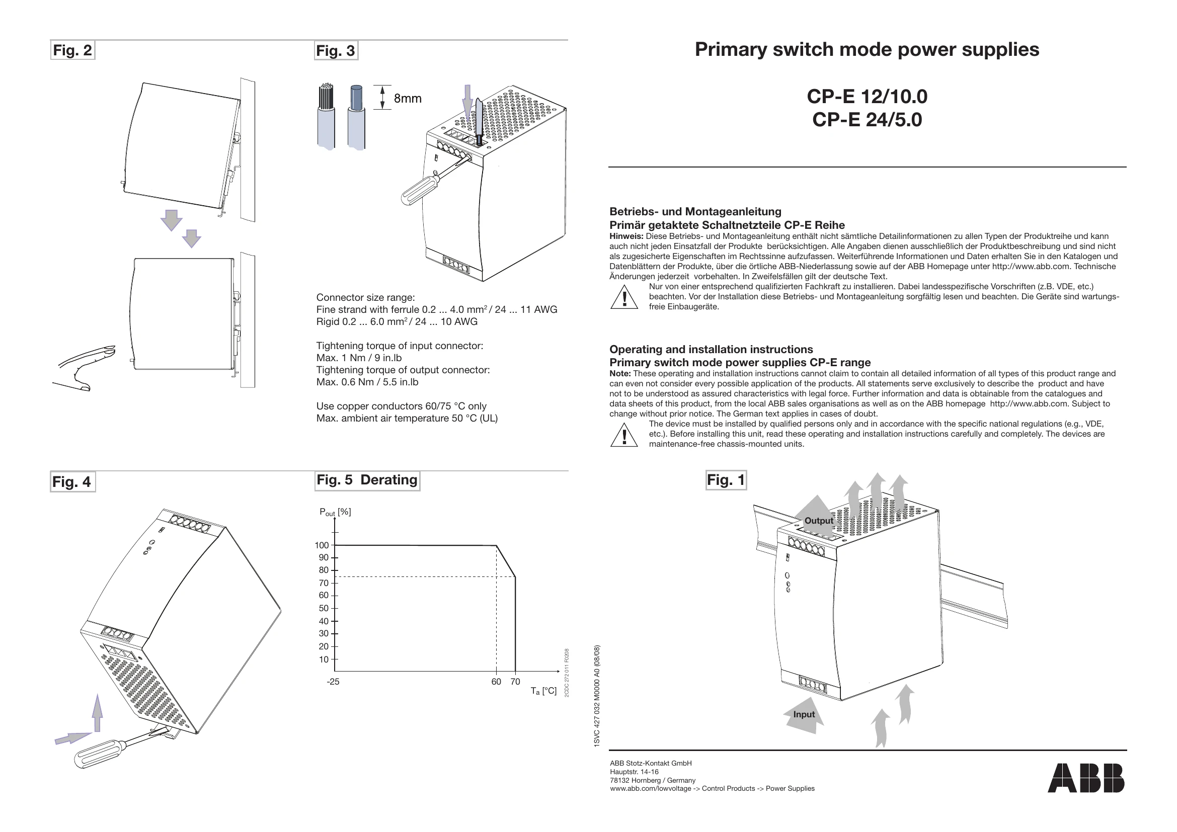
These instructions cover primary switch mode power supplies from the CP-E range. They provide essential information for safe and correct installation and operation.

Key Information:

  • Safety First: Always disconnect the system from the power supply before installation or maintenance. Ensure proper fusing and grounding.
  • Installation: Mount the unit on a DIN rail (TS35/15 or TS35/7,5) with at least 25 mm clearance on all sides. Connect cables with correct dimensioning and stripping length.
  • Operation: The green "OUTPUT OK" LED indicates normal operation (output voltage > 75%). The red "OUTPUT LOW" LED indicates low output voltage (< 70%). Use the "OUTPUT Adjust" potentiometer to set the output voltage. The "single/parallel" switch is for selecting single or parallel operation. A signaling contact (13-14) is available for 24V devices.
  • Technical Data: Covers input and output circuits, isolation data, and general operating conditions.

Always read and follow these instructions carefully. Improper installation can lead to safety hazards and device damage.

Privacy Policy