Brand: Dell
Category: Laptop
Document Type: Manual
Language: EN
Brand: Dell
Category: Laptop
Document Type: Manual
Language: EN
Uploaded: Sept. 12, 2025, 4:21 a.m.
Manual Publish Date: 2025-01-01
Refer to Dell Support Site for warranty information and service contract options.
Details on height, width, depth, and weight for different configurations.
Specifications for various Intel Core Ultra processors.
Details on the chipset.
Supported operating systems: Windows 11 Pro, Windows 11 Home, Ubuntu Linux 24.04.
Memory specifications, including type, speed, and configuration.
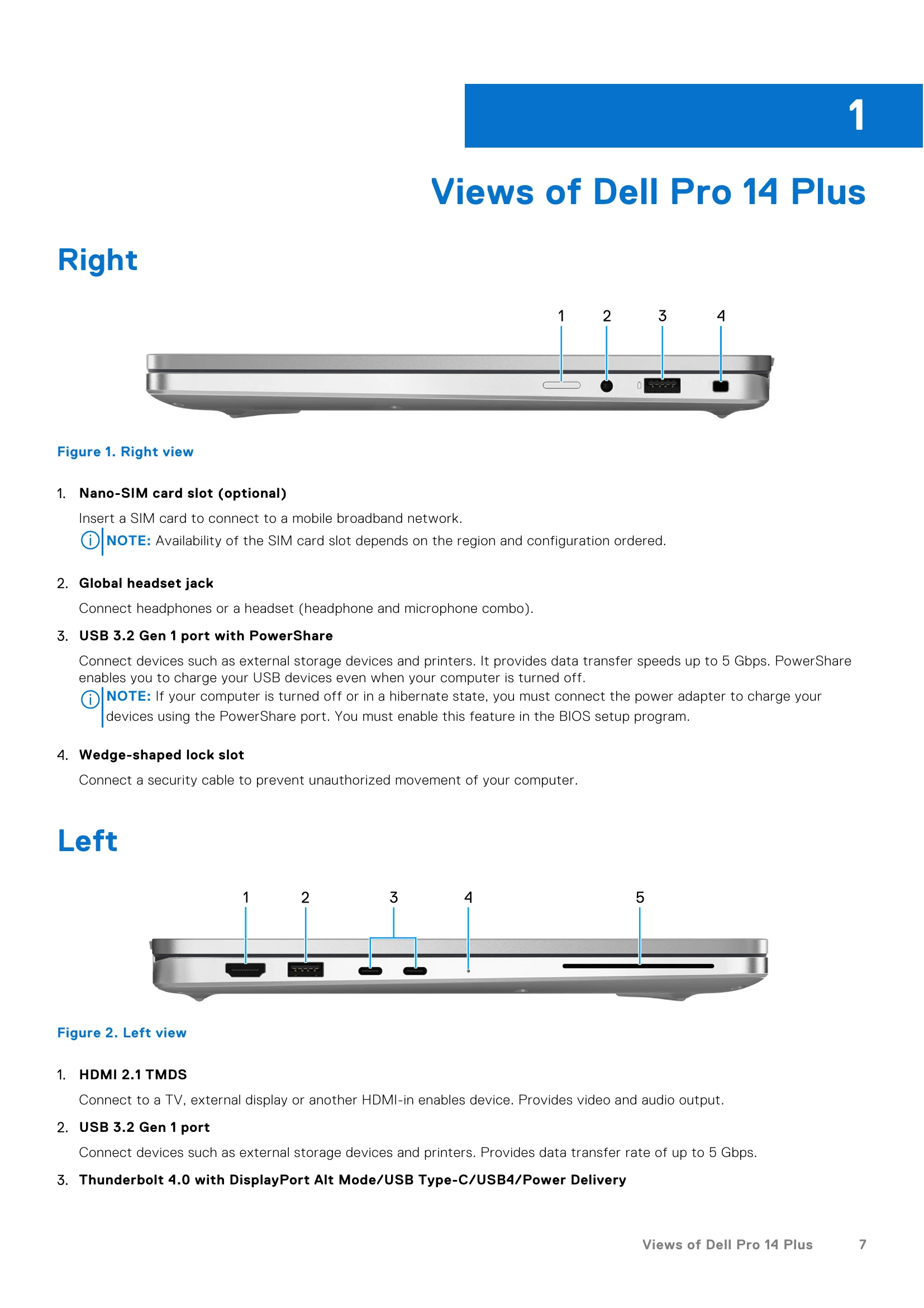
Listing of available ports and slots.
Details on internal slots like M.2.
Specifications for the WLAN module.
Specifications for the WWAN module.
Audio specifications including controller, speakers, and microphones.
Supported solid-state drive options.
Keyboard specifications, including type, layout, and shortcuts.
Camera specifications, including number of cameras, type, resolution, and viewing angles.
Touchpad specifications, including resolution, dimensions, and gestures.
| Diagnostic light codes (Amber, White) | Problem description | Recommended solutions |
|---|---|---|
| 1,1 | TPM Detection Failure | Replace the system board. |
| 1,2 | Unrecoverable SPI Flash Failure | Replace the system board. |
| 1,4 | Hinge Cable OCP | Replace LCM (cable and Panel) |
| 1,5 | EC unable to program i-Fuse | Replace the system board. |
| 1,6 | Generic catch-all for ungraceful EC code flow errors | Disconnect all power source (AC, coin cell) and drain flea power by pressing and holding down the power button. |
| 1,7 | Non-RPMC Flash on Boot Guard fused system | Flash latest BIOS version. If the problem persists, replace the system board. |
| 1,8 | Chipset "Catastrophic Error" signal has tripped | Replace the CPU. |
| 2,1 | CPU configuration or CPU failure | Replace the CPU. |
| 2,2 | System board: BIOS or Read-Only Memory (ROM) failure | Flash latest BIOS version. If the problem persists, replace the system board. |
| 2,3 | No memory or Random-Access Memory (RAM) detected | Reseat and swap memory modules among the slots. If the problem persists, replace the memory module. |
| 2,4 | Memory or Random-Access Memory (RAM) failure | Reseat and swap memory modules among the slots. If the problem persists, replace the memory module. |
| 2,5 | Invalid memory installed | Reseat and swap memory modules among the slots. If the problem persists, replace the memory module. |
| 2,6 | System board/Chipset Error | Replace the system board. |
| 2,7 | LCD failure SBIOS message | Replace the display. |
| 3,1 | CMOS battery failure | Reset the CMOS battery connection. If the problem persists, replace the RTC battery. |
| 3,2 | PCI of Video card/chip failure | Replace the system board. |
| 3,3 | Recovery image not found | Replace the system board. |
| 3,4 | Recovery image found but invalid | Replace the system board. |
| 3,5 | EC power-rail error | Replace the system board. |
| 3,6 | Flash corruption detected by SBIOS | Flash corruption is detected by SBIOS. If the problem persists, replace the system board. |
| 3,7 | Timeout waiting on ME to reply to HECI message | Replace the system board. |
| 4,1 | Memory DIMM power rail failure | Replace the system board. |
| 4,2 | CPU Power cable connection issue |
|
| 4,4 | LCD Power Rail Failure | Replace motherboard |