Brand: Electrolux
Category: Washer
Document Type: Manual
Language: EN
Brand: Electrolux
Category: Washer
Document Type: Manual
Language: EN
Uploaded: Sept. 12, 2025, 4:27 a.m.
Manual Publish Date: 2012-02-24
None
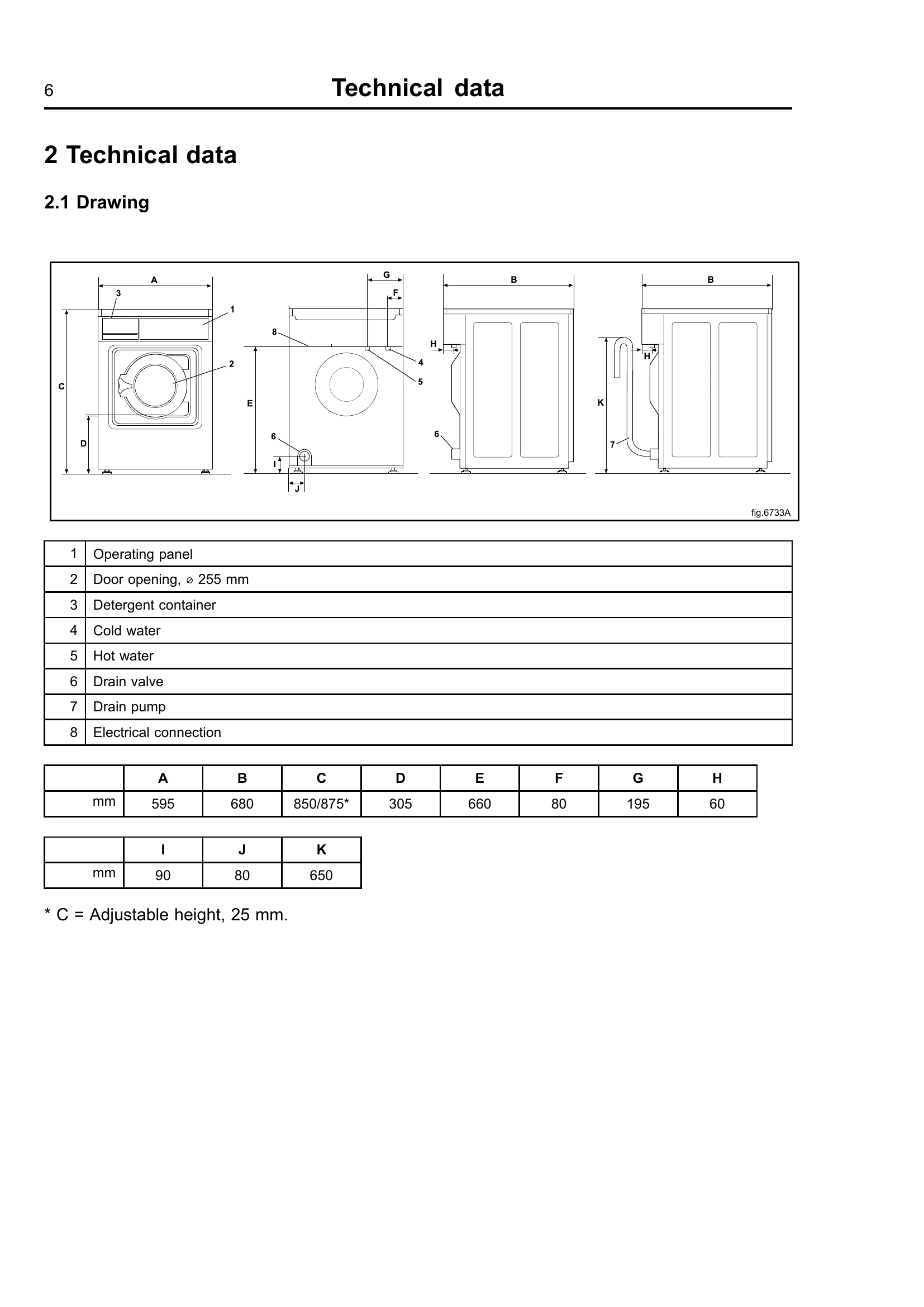
The machine consists of a door, motor, heating unit, drum, detergent container, control panel with program unit, I/O modules, and drain/drain pump.
After installation or repair, a function check is essential. This involves opening water valves, adding detergent, starting a program, and verifying normal drum rotation, absence of leaks, proper water flow through the detergent container, and that the door remains locked during operation.
The door lock system includes an actuator with a built-in micro switch for locking and unlocking, and an emergency opening button.
The motor control unit manages motor speed and acceleration/deceleration. It communicates with the program control unit and provides data on torque and load for weight calculation and unbalance detection. Caution is advised when measuring motor control circuits due to high voltages.
The heating element is responsible for heating the water. Replacement involves disconnecting power, removing panels, and carefully handling the element and its connectors.
Drum replacement is a complex procedure requiring removal of various panels, the door, lock, and hoses. The drum itself is then demounted after releasing tensioners and counterweights.
| Error Code | Description | Action |
|---|---|---|
| 21:1 HEATSINK TOO HOT | MCU cooling flange temperature too high (> 90°C) to protect transistors. | Make sure the drum turns easily. Check error code counter. Check last 8 MCU error codes. Start a 90°C program, measure motor/MCU temperature. Replace defective part. |
| 21:2 MOTOR TOO HOT | Average winding resistance indicates temperature exceeds maximum motor temperature (e.g., 150°C). | Make sure the drum turns easily. Check error code counter. Check last 8 MCU error codes. Measure three phases on MCU motor connector. Start a 90°C program, measure motor/MCU temperature. Replace defective part. |
| 21:3 NO INTERLOCK | Interlock signal missing, preventing motor drive. | Check if interlock signal is present on X302:1-2 when door lock is activated. Check bit 1 in "Motor Status". Replace defective part. |
| 21:5 MOTOR SHORT CIRCIUT | High motor current detected, MCU cuts power. | Check for short circuit in motor, winding, cables, connectors, or MCU output transistors. Check for water. Check tacho signal and interlock signal contacts. Analyze "MCU FAULT LOGGER" for SHORT CIRCUIT 1 & 2, LAST FAULT CODE, TACHO CUT-OUT. |
| 21:6 INTERLOCK HARDWARE | Inconsistent check between two interlock channels in the MCU. | Replace MCU. |
| 21:7 LOW DC VOLTAGE | Mains input voltage too low. | Check stable supply voltage (never drops below nominal - 10%). Check fuses and cables. Check supply voltage at network cabling and MCU. Analyze "MCU FAULT LOGGER" for UNDERVOLTAGE 1 & 2, LAST FAULT CODE. |
| 21:8 HIGH DC VOLTAGE | Mains input voltage too high. | Check tacho cables if many registrations in TACHO CUT-OUT registers. Analyze "FC FAULT LOGGER" for OVERVOLTAGE 1 & 2, LAST FAULT CODE. |
| 21:15 MOTOR NOT FOLLOW | Tacho sensor not working, motor rotates for max 10 seconds then stops. | Check for breaks in tacho sensor cables/connectors, motor phases, or error in tacho generator/MCU circuits. Analyze "FC ERROR LOGGER" for MOTOR NOT FOLLOW, LAST ERROR CODE, TACHO CUT-OUT. Replace defective part. |
| 21:20 NO PARAMET. SET IN MCU | Interlock is not active as read by the program unit. | Problem with hatch lock, damaged motor supply cables, or I/O board with interlock voltage. Probable source is the I/O board. |
| 40:1 I/O BOARD MISHMASH | Wrong I/O board addressed to wrong position. | Readdress all I/O boards using electric schematic. |
| 40:2 I/O INTERLOCK | Interlock not active as read from the I/O board. | Problem with hatch lock, damaged motor supply cables, or I/O board with interlock voltage. Probable source is the I/O board. |
| 40:21 I/O COMMUNICATION | CPU lost communication with one or more I/O boards. | Check I/O board configuration. Check LED, harness, connectors, and functions using electrical schematic. |
| 41:1 CHARGE CIRCUIT | Arming circuit not discharged when door lock is not to be activated. | Overloads or defective components in DLCU on I/O board 10. |
| 41:2 SET SIGNAL NO TACHO | Tacho signal not present when digital bit value from CPU is present. | Breaks in tacho sensor circuits, error in tacho magnet, or collateral damage in motor system. |
| 41:3 ACTUATOR CIRCUIT | Break (>50 kΩ) in door lock actuator circuit. | Break in cables between hatch lock and I/O board 10, error in hatch lock solenoid, or error/break in I/O board 10 circuits. If error returns after reset and is not cause by hatch lock or cables, change I/O board 10. |