Brand: EPSON
Category: Camera
Document Type: Manual
Language: EN
Brand: EPSON
Category: Camera
Document Type: Manual
Language: EN
Uploaded: Nov. 21, 2025, 7:55 p.m.
Manual Publish Date: 1999-02-16
None
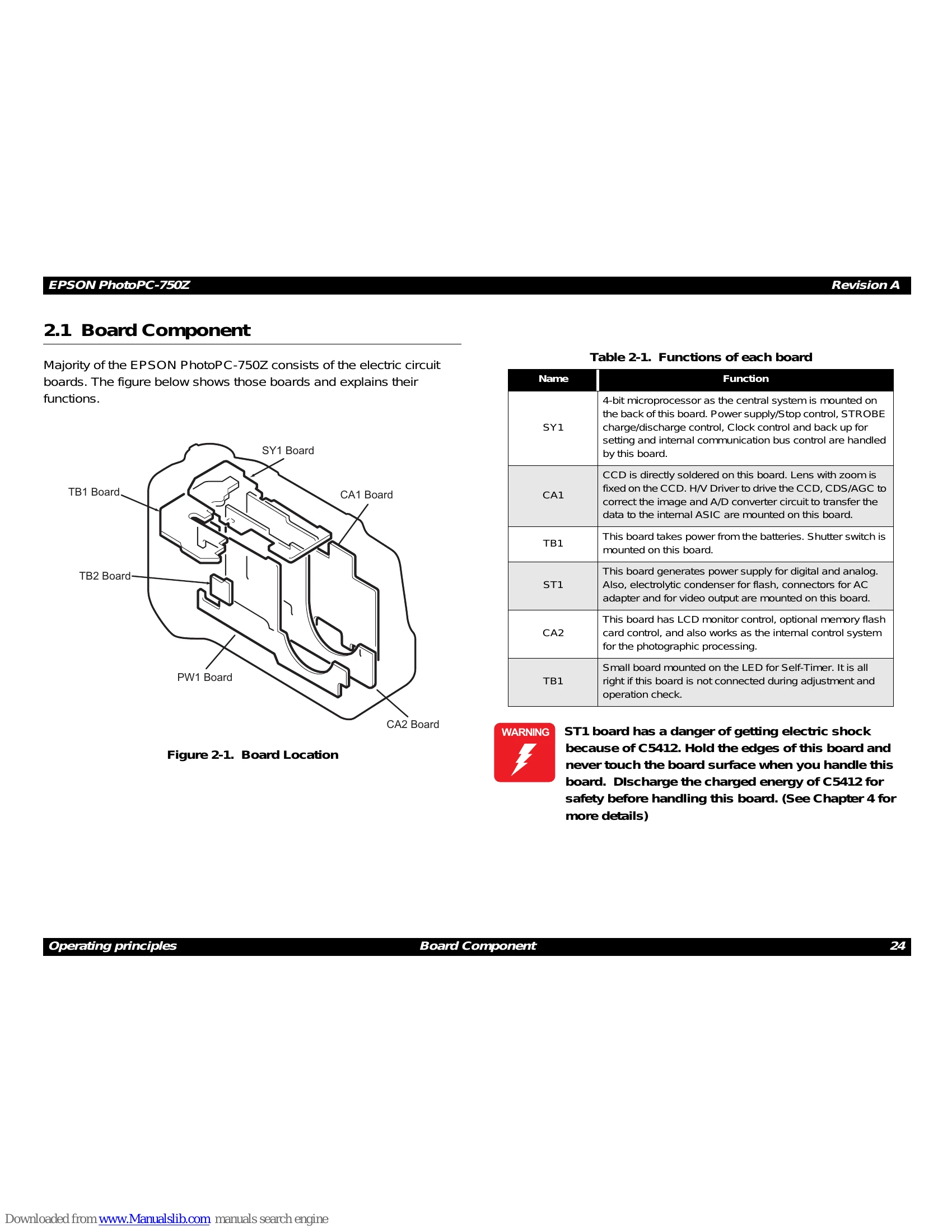
This section details the board components of the EPSON PhotoPC-750Z, outlining the structure and function of each board.
Provides a high-level overview of how the camera operates, explaining the general principles behind its functionality.
Detailed descriptions of individual circuit boards within the camera, including their roles and interconnections.
Introduces the disassembly and assembly process, including important safety precautions, required tools, and notes on screws.
Guides the user through the process of taking apart and reassembling the camera, covering cabinet parts removal and component extraction.
Details the steps for reassembling the camera, including installing parts, setting up boards, and connecting components.
Provides an introduction to the adjustment procedures and the necessary preparations.
Specific adjustment procedures for critical camera functions like flange-back, white balance, color matrix, CCD defects, and firmware updates.
| Error Code | Indication Meaning |
|---|---|
| 30s (such as 31, 32,..) | Read/Write Error to CF card (includes downloading to PC) |
| 80s (such as 81, 82,83..) | Read/Write Error to CF card (except above) |
| 60s | Read/Write Error to internal Flash |
| 90s | Data write error to the external memory |
| 100s | Data write error to internal Flash |
| 254s | Access error to the incorrect address |
| 0 | Corresponding Ch circuit does not get activated, even after 4-bit CPU on the SY1 board ouputs Wake-up signal to the PW1. |