Brand: GE
Category: Washer
Document Type: Manual
Language: EN
Brand: GE
Category: Washer
Document Type: Manual
Language: EN
Uploaded: Nov. 21, 2025, 8:38 p.m.
Manual Publish Date: 2020-04-27
Refer to the warranty information section for details on the warranty period and coverage.
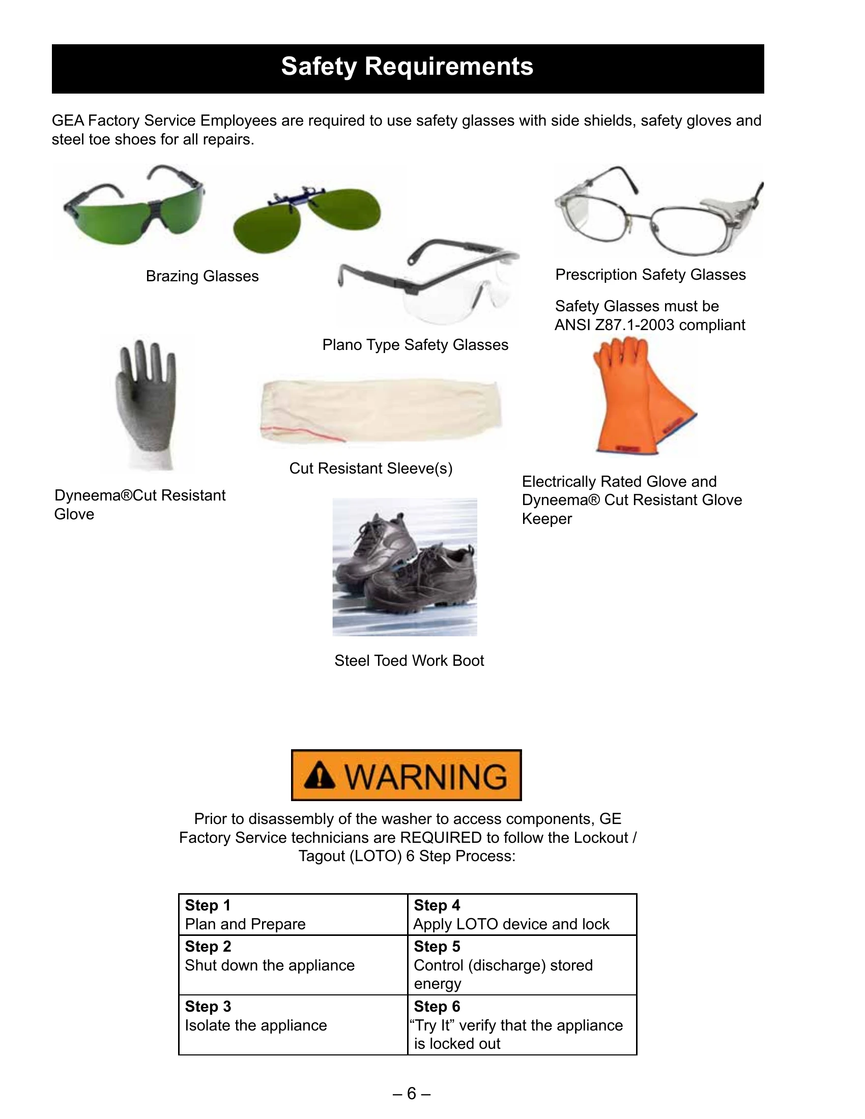
This manual covers GE UltraFresh Front Load Washers. It provides information on safety requirements, specifications, control features, and operation.
Quick Start: Load clothes, close door, power on, select cycle, add detergent, and press start. After the cycle, use ULTRAFRESH VENT to eliminate moisture.
Display and Status Indicators: Shows remaining time, cycle status (Fill, Wash, Rinse, Spin), and icons for Wi-Fi, Venting, Control Lock, Door, SmartDispense (Auto, More, Less), Tank Low, and Loads Left.
Washer Features: Details various wash cycles (Normal, Whites, Heavy Duty, etc.), temperature settings, soil levels, and spin speeds.
Using the Washer: Explains the dispenser drawer, SmartDispense™ system, and how to use detergent, fabric softener, and bleach compartments.
Maintenance: Includes instructions for cleaning the drain pump filter.
| Fault Code | Description | Trigger Condition | Action |
|---|---|---|---|
| 0 | No Faults | Displayed in Service Mode only when there are no faults to display. | • Displayed when no faults are found. |
| 1 | Lock Monitor | This fault is set if the motor shaft speed exceeds 45 RPM for 5 seconds while in spin mode and unlocked. This fault can also occur if the basket is manually spun by hand. | • Check the door lock using Service Mode spin test 14. • Check door lock harness connectors both at the main board and at the door lock assembly. • Replace door lock if this happens frequently. |
| 2 | Door Monitor | Control did not get Door closed signal from switch while motor was moving. Could mean the switch didn't close or control didn't get the signal because of lack of connection. | • Check the door lock using Service Mode spin test 14. • Check door lock harness connectors both at the main board and at the door lock assembly. • Replace door lock if this happens frequently. |
| 3 | Locked Rotor Monitor | For 5 straight seconds control not seeing signal changes indicating the motor is turning while trying to spin. Could mean the motor isn't rotating or control didn't get the signal because of lack of connection. | • Physically check the washer for anything preventing motor movement. • Verify hall sensor is connected to the main harness. Put washer in Service Mode and run test 14 (Spin). If hall sensor is bad or disconnected, the basket will start to spin normally and then stop spinning after approximately 5 seconds. Ensure hall sensor is properly connected and positioned on the motor. If basket spins for approximately 15 seconds, the hall sensor is most likely NOT the cause. • Measure the resistance of each motor phase winding, If TCO is tripped, wait approximately 45 minutes for TCO to reset and make sure motor moves freely and that nothing is jamming it, replace motor if it does not. • Check the door lock using service mode spin test 14. • If unit doesn't spin, replace inverter board or the main board. |
| 6 | Critical Flood Level by Pressure | Control received an extended period of pressure readings that is nearing over-flow levels. Voltage Output must be present. Could mean water did get that high due to briefly stuck water valve. Voltage output of sensor too high for actual water level because of sensor or water in pressure tube increasing pressure. | • Check pressure tube for pinches where it goes through main board. • Check pressure tube for trapped water. • Check water valve operation and for any leaking water valves. • Use pressure sensor test 10 to ensure correct pressure sensor operation. • Ensure pressure chamber port is free from obstruction using drill bit size 1/16-in. by hand so as not to drill through the inner wall. |
| 8 | Pressure Sensor Loss | Determines if appropriate pressure changes are seen during fill. It assumes there is a pressure leak, a clog in the pressure hose/system delaying the increase in pressure, or a significant amount water leaking out. | • Check to make sure house water supply valves are turned on. • Check water valve operation. • Check pressure tube for pinches where it goes through top cover grommet. • Use pressure sensor test 10 to ensure correct pressure sensor operation. • Check pressure tube for trapped water. • Ensure pressure chamber port is free from obstruction using drill bit size 1/16-in. by hand so as not to drill through the inner wall. |
| 9 | Door Switch Redundancy | Three cycles have been completed without any door opening. | • Open and close the door to clear the fault. • Check harness and connectors that go to the door switch. • Use test 13 to ensure system can detect the correct door state with the Spin and Rinse LED's. • Consumer education that four cycles cannot be run back-to-back without opening and closing the door. • If the fault will not clear, replace the door lock. |
| 15 | Water Temp Sensor Invalid | The thermistor is disconnected, not present, or has failed. | • Run Service Mode heater and thermistor test 20 to verify heater and thermistor. • Check thermistor resistance from connector J701 on the control board. Validate the resistance matches the table in mini-manual. • Check the heater resistance from connector J503 on the control board from pin 4 to 5. • Check wiring harness and connections. • Replace thermistor or heater if resistance is out of spec. |
| 17 | Dry Load Sense Timeout | Dry load sense times out and moves to the next part of the cycle selected. This occurs when the washer is not reaching the target speed within a defined time limit for the load type selected. | • Check for water in the bottom of the tub. If so, drain and try cycle again. • Check the basket for excessive friction. Basket should spin freely. If not, find source of friction and remove it. • This can also happen if a cycle is started with wet clothes. • Consumer education to doesn't load the washer with wet clothes. |
| 18 | Drain Pump Clearing Algorithm Failed | Pressure sensor indicates water in the tub after attempting to drain. | • Fill tub using Service Mode test 7 and check drain pump operation using Service Mode test 12. • Check drain hose for blockages. • Confirm standpipe height is within recommended guidelines. • If pump does not operate, check that the resistance of the pump matches resistance table and verify 120 VAC while pump is operating at J512. • Check pressure tube for pinches where it goes through top cover grommet. • Use pressure sensor test 10 to ensure correct pressure sensor operation. |
| 19 | UI State Timeout | This will happen if a cycle is paused for greater than 24 hours or if the pressure sensor reads greater than 0.5-in. while the machine is off for greater than 24 hours. | • Check for leaking water valves. • Use pressure sensor test 10 to ensure correct pressure sensor operation. • Consumer education on leaving sopping wet items in basket for more than 24 hours. • Pausing the machine for greater than 24 hours can cause this. • Can be caused by out-of-balance. • Can be caused by starting a cycle with the "no spin" option selected. • Check the output voltage from the pressure sensor to ensure it matches the water level in the basket according to the pressure sensor chart. • Check pressure tube for trapped water. • Ensure pressure chamber port is free from obstruction using drill bit size 1/16-in. by hand so as not to drill through the inner wall. |
| 20 | Critical Flood Level by Gallons | Water volume into the tub exceeded 41 gallons as calculated by the control. 1. Pressure tube is momentarily pinched, has water in it, partial blockage if Flood fault 12 occurs. 2. Low water pressure/ flow or permanent pressure system blockage if NO Flood fault 12 occurs. | • Check pressure tube for pinches where it goes through top cover grommet. • Check for any leaking water valves. • Check home water pressure. • Check the output voltage from the pressure sensor to ensure it matches the water level in the basket according to the pressure sensor chart. • Check pressure tube for trapped water. • Ensure pressure chamber port is free from obstruction using drill bit size 1/16-in. by hand so as not to drill through the inner wall. |
| 22 | Out of Balance (OOB) During Dry Load Sense | Large wet/OOB load being washed. This is set if OOB condition is detected during dry load sense algorithm. Dry load sense will be abandoned and wet load sense will be started. | • Check for excessively OOB load. Customer Education on how to distribute load. • Check the basket for excessive friction or for being excessively out of round. Basket should spin freely and without wobble. If friction is found, remove it. If basket is bad, replace it. • Check speed sensor for loose connection to the motor. |
| 23 | Critical Door Lock Failure | Cycle canceled due to inability to reach desired door lock state. | • Verify the door is closed properly, if door does not close freely, lift the door until it closes freely. • Replace door lock and door lock harness then run below actions. • Check the door lock using service mode spin test 14 to ensure door lock operation. • Verify that the door lock is not blocked by any external debris. • Check door switch continuity at J513 on the control. • Check continuity of door lock position. Opened or Closed. • Check for proper operation of door lock. 120 VAC while activating. • Check door lock wiring harness from the control to lock assembly. |
| 24 | Door Logic Failure | Door lock failure. This fault is set if the system perceives the door to be both OPEN and LOCKED for 5 consecutive seconds. | • Replace door lock and door lock harness, then run below actions. • Check the door lock using Service Mode spin test 14 to ensure door lock operation. • Check harness and connections from the control to the door lock assembly for damage and continuity. • Run a spin cycle. Pull up on the door during spin for more than 5 seconds and see if this fault occurs. |
| 25, 65 | Pressure Sensor Dropout, Pressure Sensor Continuous Gallons Monitor | This fault is set when the pressure is above 6-in., then later drops to less than 1-in. for 5 seconds without draining. | • Check to make sure house water supply valves are turned on. • Check water valve operation. • Check for proper drain pipe and stand pipe height. • Check pressure tube for pinches where it goes through control board. • Use pressure sensor test 10 to ensure correct pressure sensor operation. • Check pressure tube for trapped water. • Ensure pressure chamber port is free from obstruction using drill bit size 1/16-in. by hand so as not to drill through the inner wall. |
| 26 | Out of Balance (OOB) Ended Final Spin | Washer detected an out of balance load and was unable to reach final target spin speed. | • Run Drain & Spin cycle to ensure basket reaches final spin speed and the Spin LED does not blink (a blinking Spin LED indicates that an out of balance was detected during final spin). • Check for any basket loose or damage or abnormal noise. • Check to make sure unit is firmly seated on all four legs, doesn't rock, and is leveled. • If washer spins properly, educate consumer on how to properly load and distribute their clothes in the washer basket to prevent an OOB. |
| 27 | IMP Overheated | Inverter over temperature (> 221°F) for 5 seconds | • Check whether drum is easy to tumble. • Check that motor has no signs of over temperature. • Reset inverter board by unplugging washer for 30 seconds. Run a drain and spin by selecting Rinse+Spin cycle and select no rinse by pressing Rinse until both Extra and Normal lights turn off. • Enter Service Mode and check that fault has cleared. • If fault persists, or unit does not spin, replace inverter board. |
| 29 | Drive System Self-Check Fault | MCU failed self-check. One fault over the checking process (ROM, RAM, CPU Registers, Stack, Clock) triggers the fault. The self-checking is continuously performed by MCU. | • Run a spin test in service mode to verify motor operation. • If no movement, check rotor, stator, harness and connectors for damage. • If above components are good, replace inverter board. |
| 30 | Main Board Over Voltage | When connected to power, voltage is higher than 160 VAC. | • Check if the voltage is higher than 160V. • If voltage is normal, replace the main control board. |
| 31 | Main Board Self Check Failed | MCU failed self-check. One fault over the checking process (ROM, RAM, CPU Registers, Stack, Clock, AD) triggers the fault. The self-checking is continuously performed by MCU. | • Check door lock, door switch, water temperature sensor. • Check harness and connections. • If above is checks good, replace the main control board. |
| 32, 77 | Critical door Lock Failure: Can't Unlock Door | Cycle canceled due to inability to unlock door. | • Verify the door is closed properly, if door is not close freely, lift the door until close free. Replace door lock and door lock harness then run below actions. • Check the door lock using Service Mode spin test 14 to ensure door lock operation. • Verify that the door lock is not blocked by any external debris. • Check door switch continuity at J513 on the control. • Check continuity of door lock position. Opened or Closed. • Check for proper operation of door lock. 120 VAC while activating. • Check door lock wiring harness from the control to lock assembly. |
| 33, 34, 41, 42, 43, 44, 45, 46, 47, 48, 49, 50, 51, 66, 67, 68, 69, 71, 72, 73, 74, 83 | Inverter Fault | Any of these faults can be set if the inverter board reports a fault. | • Run Service Mode spin test 14 to full completion. If cycle fully completes, no further action required. • Check line voltage for 102 VAC to 132 VAC. • Check all inverter board harness connections. • Check motor TCO continuity at J502 (inverter board). If open, should reset after 45 minutes. • Check for continuity through each pair of motor phase windings. If any windings found open, replace motor. • If the above repair actions don't clear the fault, replace inverter board. |
| 35, 59, 60, 61, 63, 64 | Accelerometer Faults | Any of these faults can be set if the accelerometer board reports a fault. | • Run Service Mode spin test 14 to full completion. If cycle fully completes, no further action required. • Check accelerometer board harness connections. • If the above repair actions don't clear the fault, replace accelerometer board. |
| 37 | Heater | Fault is set if the thermistor doesn't see at least 3 degrees Fahrenheit heat rise after the heater has been on for 5 minutes. | • Run Service Mode heater and thermistor test 20 to verify heater and thermistor. • Check thermistor resistance from connector J701 on the control board. Validate the resistance matches the table in mini-manual. • Check the heater resistance from connector J503 on the control board from pin 4 to 5. • Check wiring harness and connections. • Replace thermistor or heater if resistance is out of spec. |
| 38, 39, 40, 84 | Vent Damper | Fault is set if close/open feedback is not fails after 5 seconds. | • Run Service Mode damper test 24 to verify feedback open/close. • Check wiring harness and connections. Replace damper if damper feedback open/close is not detected. |
| 57 | Door Lock Fault Water Above Door by Pressure | This fault is set when door is unlocking while water level detected by pressure sensor is above than threshold. | • Check pressure tube for trapped water. • Check each valves operation. (Replace water valve and send back to GE Appliances.) • Use pressure sensor test 10 to ensure correct pressure sensor operation. • Check pressure tube for pinches where it goes through top cover grommet. • Ensure pressure chamber port is free from obstruction using drill bit size 1/16-in. by hand so as not to drill through the inner wall. |
| 58 | ADC Health Check Fault | After drain control should go to idle End Cycle ADC Health Check Fault. This fault is set when any ADC Self-Diagnosis channel reports an out-of-tolerance value for 10 seconds. | • Replace main board. |
| 62 | Inverter Power And Door Lock Monitor | The fault is set when the system request inverter power full and the door in unlocked for more than 5 seconds. | • See Fault Code 2. |
| 70 | Inverter Volt/ Hertz Start Up | Inverter volt hertz star up 135 is set five times in one cycle. | • Review voltage and frequency at supply line. • Replace the inverter. |
| 77 | See Fault Code 32 | See Fault Code 32 | • See Fault Code 32 |
| 78 | Board Communication API Mismatch | The Main Board detects that it doesn't have the same API version as another board. | • Update software |
| 85 | Voltage Detected by MC | Voltage detected by MC is outside acceptable window | • Review voltage and frequency at supply line. • Replace the Main Control board. |