Brand: Honeywell
Category: Other
Document Type: Manual
Language: EN
Brand: Honeywell
Category: Other
Document Type: Manual
Language: EN
Uploaded: Nov. 21, 2025, 6:08 p.m.
Manual Publish Date: 1976-02-01
The Level 6 minicomputer system is designed for simplicity, reliability, and performance. It features an open-ended architecture, modular software, and low-cost peripherals, making it suitable for various applications.
Peripherals are controlled by the system software. Actions are initiated through input/output commands. Error codes are provided for troubleshooting, with detailed explanations in the GCOS/BES Operators Guide.
To operate the system, all power supplies must be turned on in the following order: Power Distribution Unit, Central Processor, Memory Save and Autorestart (optional), and Peripherals.
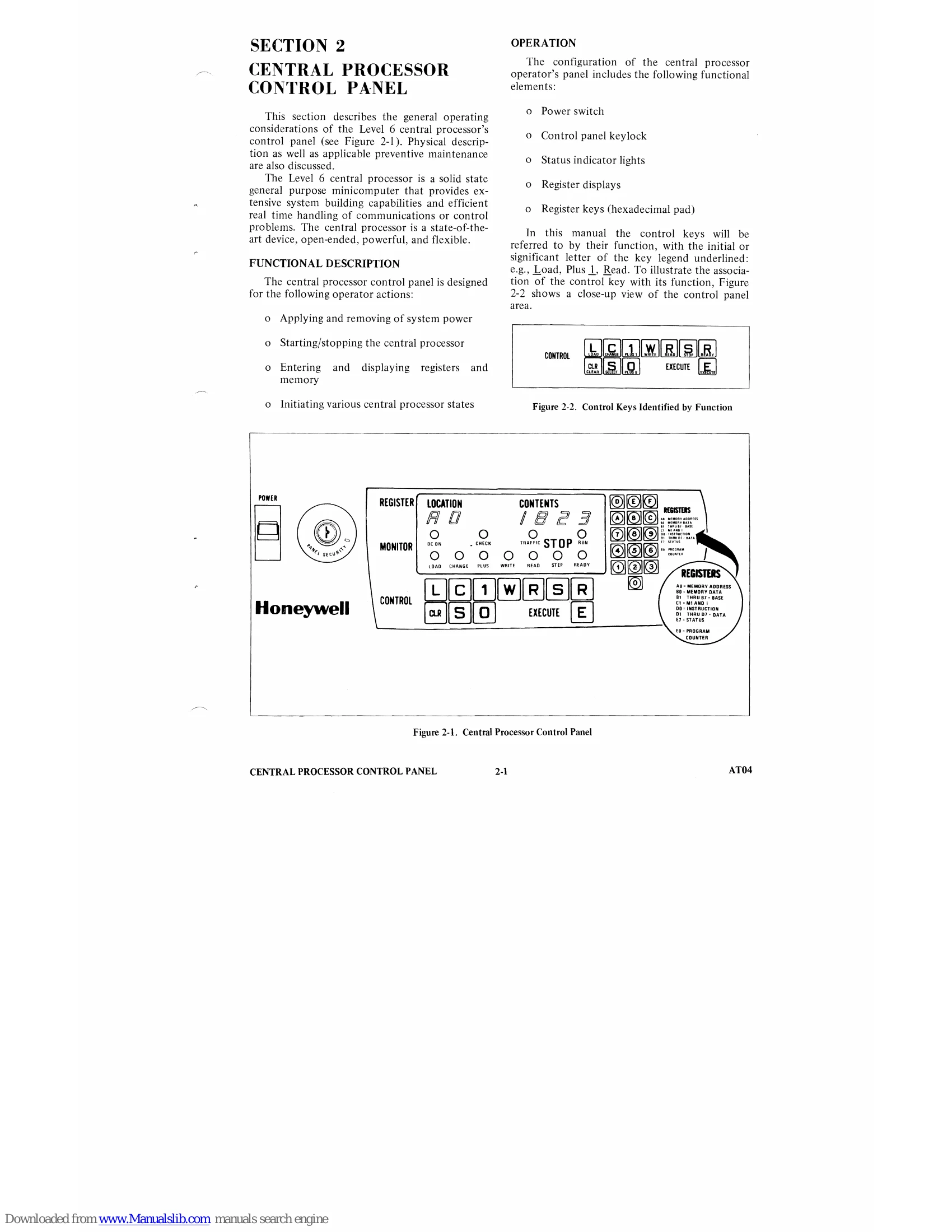
The central processor control panel allows operators to apply/remove power, start/stop the processor, enter/display registers and memory, and initiate various processor states. It includes a power switch, keylock, status indicators, register displays, and hexadecimal keys.
| Key | Function | Key Color | Description |
|---|---|---|---|
| L | Load | Green | Depress the Load key to place the processor in the Load Mode. Depressing the E key will bootload a program into memory. |
| C | Change | Green | Depress the Change key to place the processor in the Change Mode. In this mode the processor is ready to accept operator modifications to the contents of selected registers. |
| 1 | Plus 1 | White | Depress the Plus 1 key to place the processor in Plus 1 Mode. In this mode the processor is ready to read or write successive memory locations from the control panel, and each depression of the E key causes the memory address register to be incremented by 1. |
| W | Write | White | Depress to place the processor in Write Mode. In this mode the processor Writes the contents of the selected register into the location addressed by the memory address register (AO). |
| R | Read | White | Depress the Read key to place the processor in the Read Mode. In the Read Mode the processor reads the contents of the selected register from the location addressed by the memory address register (AO). |
| S | Stop | Red | Depress the Stop key to stop instruction execution and place the processor in the Stop State. In this state each depression of the E key causes execution of one instruction so that the operator may step through a program. |
| R | Ready | Red | Depress the Ready key to place the processor in the Ready Mode (Ready indicator ON). In this mode the processor is ready to execute. If the E key is depressed program execution begins and the RUN indicator illuminates. |
| CLR | Master CLeaR |
Black | Depress the CLR key to clear the processor. This action resets the instruction register (DO) and the program counter (EO) to zero and clears any order pending in the processor. Master clear can be performed only in the STOP State. |
| S | Select | Green | Depress the Select key to place the processor in the Select Mode. The register to the operated on is selected by keying in the proper selection code from the hexadecimal pad. |
| 0 | Plus 0 | White | Depress the 0 key to reset the Plus 1 Mode. In this mode the memory address register cannot be modified during a memory read or write from the control panel. |
| E | Execute | Black | Depress the E key to place the processor in the Run State. In this state the processor executes instructions starting at the location specified by the program counter. Execution continues until the S key is depressed or up to the first halt instruction. |