Brand: Honeywell
Category: Security System
Document Type: Installation Guide
Language: EN
Brand: Honeywell
Category: Security System
Document Type: Installation Guide
Language: EN
Uploaded: Nov. 21, 2025, 8:40 p.m.
Manual Publish Date: 2010-09-10
For the latest warranty information, please go to: www.honeywell.com/security/hsc/resources/wa
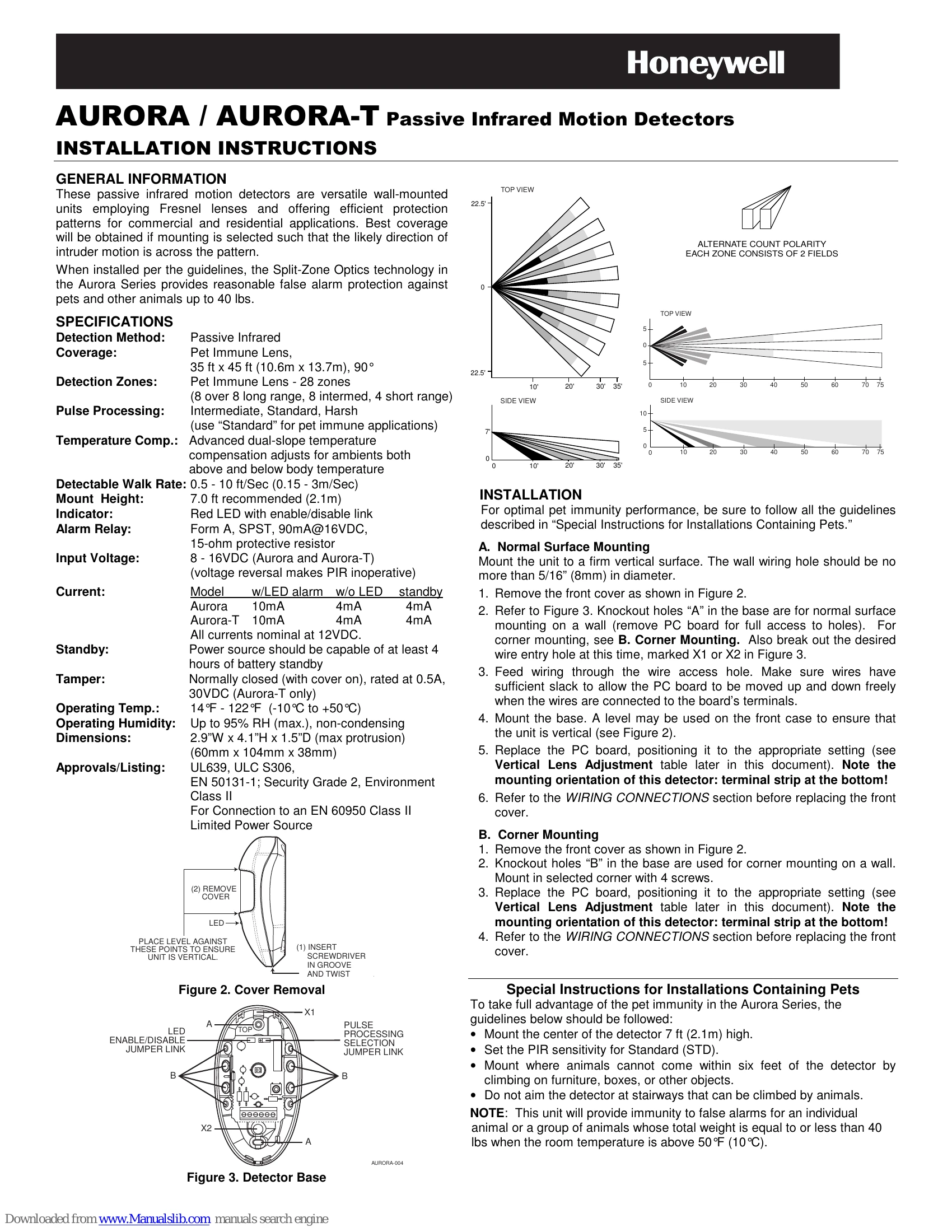
These passive infrared motion detectors are versatile wall-mounted units employing Fresnel lenses and offering efficient protection patterns for commercial and residential applications. Best coverage will be obtained if mounting is selected such that the likely direction of intruder motion is across the pattern.
When installed per the guidelines, the Split-Zone Optics technology in the Aurora Series provides reasonable false alarm protection against pets and other animals up to 40 lbs.
1. Normal Surface Mounting: Mount the unit to a firm vertical surface. Remove the front cover, break out wire entry holes, feed wiring, mount the base ensuring the unit is vertical, replace the PC board, and connect wiring.
2. Corner Mounting: Remove the front cover, use knockout holes for corner mounting, mount with screws, replace the PC board, and connect wiring.
To ensure optimal pet immunity, follow these guidelines:
Note: This unit provides immunity for animals totaling 40 lbs or less when room temperature is above 50°F (10°C).
| Condition | Cause | Remedy |
|---|---|---|
| Intermittent Alarm (LED Operative) | A. Rapid temperature change. | Locate source and reposition detector. |
| B. Drafts causing movement of objects. | Eliminate source of motion. | |
| Intermittent or Continuous Alarm | A. Inadequate DC voltage or reversed polarity. | Ensure correct polarity, adequate voltage, secure wiring, and connections. |
| B. Protective loop is interrupted (open). | Check protective loop wiring or detector relay contacts. Check continuity. If absent, return unit. If present, check loop wiring. | |
| LED Inoperative | A. LED jumper link ON. | Remove LED jumper link. |
| B. LED malfunction. | Check for broken/shorted leads. Return unit for replacement. | |
| Detection Area Changes | A. Repositioned furniture or equipment. | Caution customer about layout changes. Reposition detector. |
| B. Mounting surface is unstable. | Mount on a secure surface. | |
| Panel Indicates Continuous Fault In Zone Of Protection Containing PIRS (PIR's alarm LED not lit) | Too many detectors in the zone, exceeding allowable loop resistance. | Reduce the number of detectors in the zone. |