Brand:
LG
Category: TV
Document Type: Parts/Service
Language: EN
Brand:
LG
Category: TV
Document Type: Parts/Service
Language: EN
Uploaded: Nov. 21, 2025, 7:06 p.m.
None
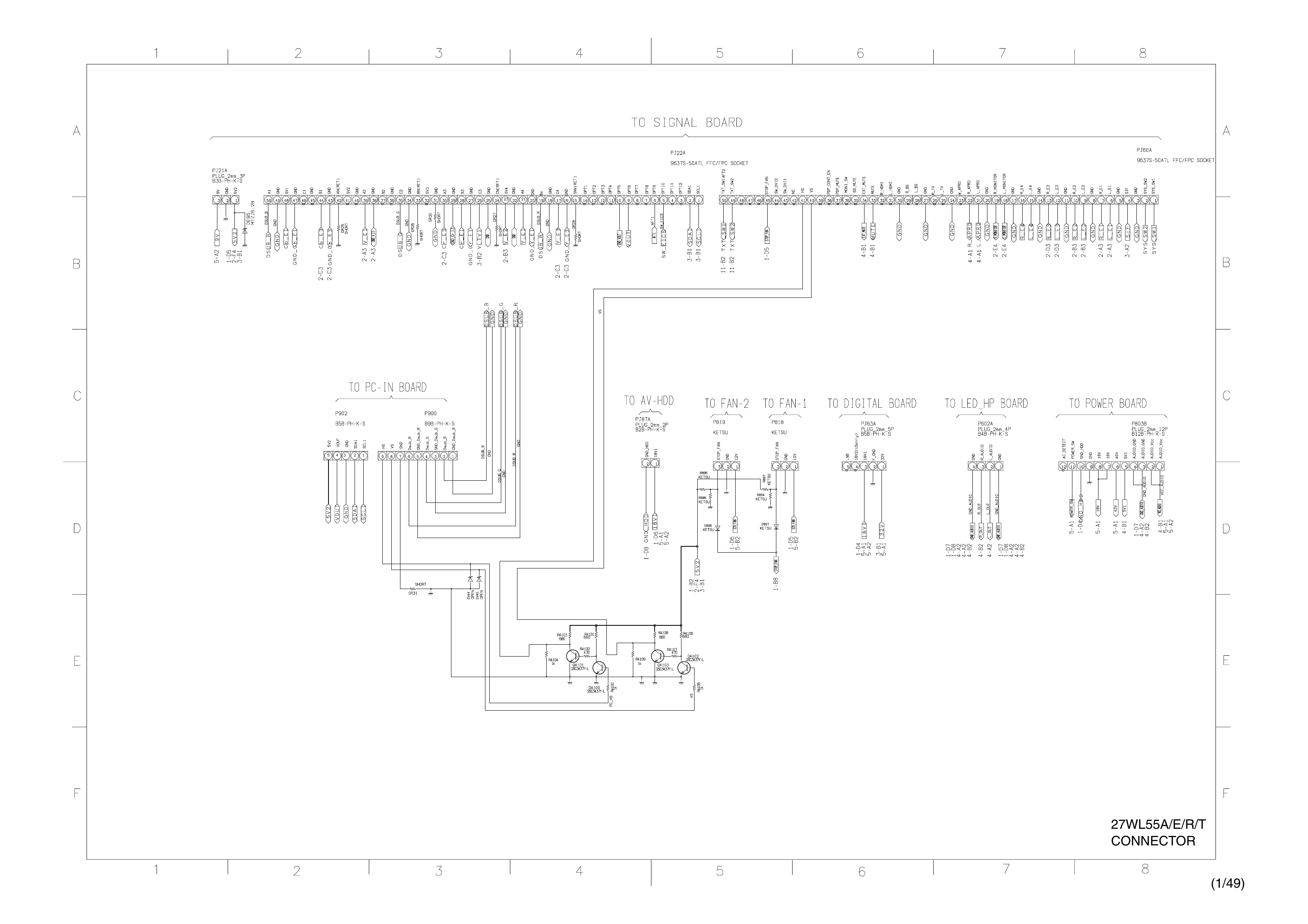
This manual provides schematic diagrams and structure for the LG 27WL55A/E/R/T television. It details the connections and components across various boards, including the AV board, Signal board, PC-IN board, LED HP board, and Power board.
Key sections cover:
Important notes regarding component identification (resistors, capacitors) and safety precautions are also included.
| NOTE | Description |
|---|---|
| 1. RESISTOR | Resistance is shown in ohm [K = 1.000, M = 1.000.000]. All resistors are 1/6W and 5% tolerance carbon resistor, unless otherwise noted. Options include 1/2R (Metal or Metal oxide of 1/2 watt), 1RF (Fuse resistor of 1 watt), 1/2S (Carbon composition of 1/2 watt), 10W (Cement of 10 watt). Tolerances: K = ±10%, G = ±2%, F = ±1%. |
| 2. CAPACITOR | Unless otherwise noted in schematic, all capacitor values less than 1 are expressed in µF, and values more than 1 in pF. All capacitors are ceramic 50V, unless otherwise noted. Symbols are provided for Electolytic and Mylar capacitors. |
| 3. The parts indicated with "△" have special characteristics, and should be replaced with identical parts only. | Identical part replacement is critical for safety. |
| 4. Voltages read with DIGITAL MULTI-METER from point indicated to chassis ground, using a color bar signal with all controls at normal, line voltage 220 volts. | Standard voltage measurement procedure. |
| 5. Waveforms are taken receiving color bar signal with enough sensitivity. | Waveform measurement procedure. |
| 6. Voltage reading shown are nominal values and may vary ±20% except H.V. | Tolerance for voltage readings. |