Brand: Miele
Category: Oven
Document Type: Parts/Service
Language: EN
Brand: Miele
Category: Oven
Document Type: Parts/Service
Language: EN
Uploaded: Nov. 21, 2025, 7:37 p.m.
Manual Publish Date: 2018-03-07
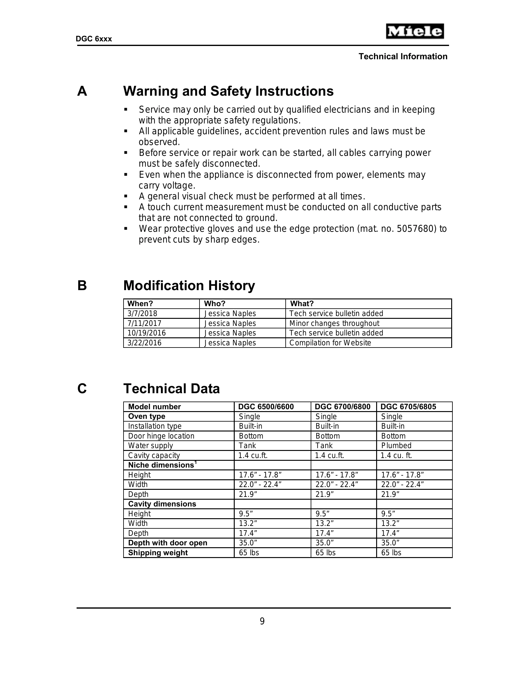
Service must be performed by qualified electricians according to safety regulations and laws.
| Submenu | Function/Description | Option |
|---|---|---|
| Fault memory | F0000 | No faults |
| F0001, etc. | All faults registered are displayed one after the other. Press the touchpad next to a fault code. The fault code is displayed. | |
| Component | Delete fault memory | All stored fault codes are deleted. |
| H3-2 cavity lighting | Start/Stop switch state 0/1 | |
| R13 top heater element | Start/Stop switch state 0/1 | |
| R12 bottom heater element | Start/Stop switch state 0/1 | |
| R14 convection element | Start/Stop switch state 0/1 | |
| R15 broil element | Start/Stop switch state 0/1 | |
| M2-1 cooling fan | Level 1, Level 2 | |
| M2-2 convection fan | Level 1, Level 2 | |
| M28 air flap motor | Start/Stop switch state 0/1 | |
| M7 feed pump | Start/Stop switch state 0/1 | |
| 1R25 steam generator heater element¹ | Start/Stop switch state 0/1 | |
| 2R25 steam generator heater element¹ | Start/Stop switch state 0/1 | |
| 3R25 steam generator heater element¹ | Start/Stop switch state 0/1 | |
| 1R25-2R25 steam generator heater elements | Start/Stop switch state 0/1 | |
| M8 drain pump | Start/Stop switch state 0/1 | |
| M29 pinch/drain valve | Start/Stop switch state 0/1 | |
| Sensor values² | 2M2-1 heat-flow fan | On/Off |
| R30-10 heat-flow sensor | e.g., 21°C | |
| R30-12 roast probe | e.g., 0°C (if roast probe is in its holder) | |
| 2R30-10 heat-flow air channel temperature sensor | e.g., 21°C | |
| R30-34 cooling-air temperature sensor | e.g., 21°C | |
| R30-22 bottom heat temperature sensor | e.g., 21°C | |
| SLT (control-power electronic) | e.g., 26°C | |
| Switch status | S24 (door contact switch). Open or close the door. | 1: Switch closed; door open. 0: Switch open; door closed. |
| E1-2 (fill-level electrode) | 0: Switch open. Water is in the steam generator. 1: Switch closed. No water in the steam generator. | |
| B3-17 (fill-level sensor). Fill the water tank (the tank on the right) to the descale mark and then insert it. | 1: Switch closed. Water tank is installed and full. 0: Switch open. Water tank is uninstalled or installed but empty/not full. | |
| B3-18 (water tank sensor). Insert or remove the water tank (the tank on the right). | 1: Switch closed. Water tank is installed. 0: Switch open. Water tank is not installed. | |
| B3-19 (condensate tank sensor). Install/Remove the condensate tank. | 1: Switch closed. Condensate tank is installed. 0: Switch open. Condensate tank is not installed. | |
| B1-2 (drain pump reed switch) | 1: Switch closed. Pump activated. 0: Switch open. Pump not activated. | |
| M28 (air flap) | 1: Switch closed. 0: Switch open. | |
| S60 (lift panel position switch). Open or close the fascia manually or by pressing the Lift Panel button. | 1: Lift panel is out and up or all the way in. 0: Lift panel is straight out. | |
| M29 (pinch valve) | 1: Pinch valve closed. 0: Pinch valve open. | |
| Operating hours (total) | The total machine operating hours figure is displayed. | |
| Operation | Display | The display flashes white and the sensors next to the display flash yellow. |
| Display backlight | Backlight test is displayed and the display changes from dark to light. | |
| Buzzer/Loudspeaker (Touch) Sensors | The buzzer is activated. A sensor test is carried out where different values are displayed when the various touchpad sensors are activated. | |
| Exit | Quit service mode? | Yes/No |