Brand: Panasonic
Category: Home Theater System
Document Type: Manual
Language: EN
Brand: Panasonic
Category: Home Theater System
Document Type: Manual
Language: EN
Uploaded: Nov. 21, 2025, 7:22 p.m.
Warranty information is not explicitly detailed as a period in months.
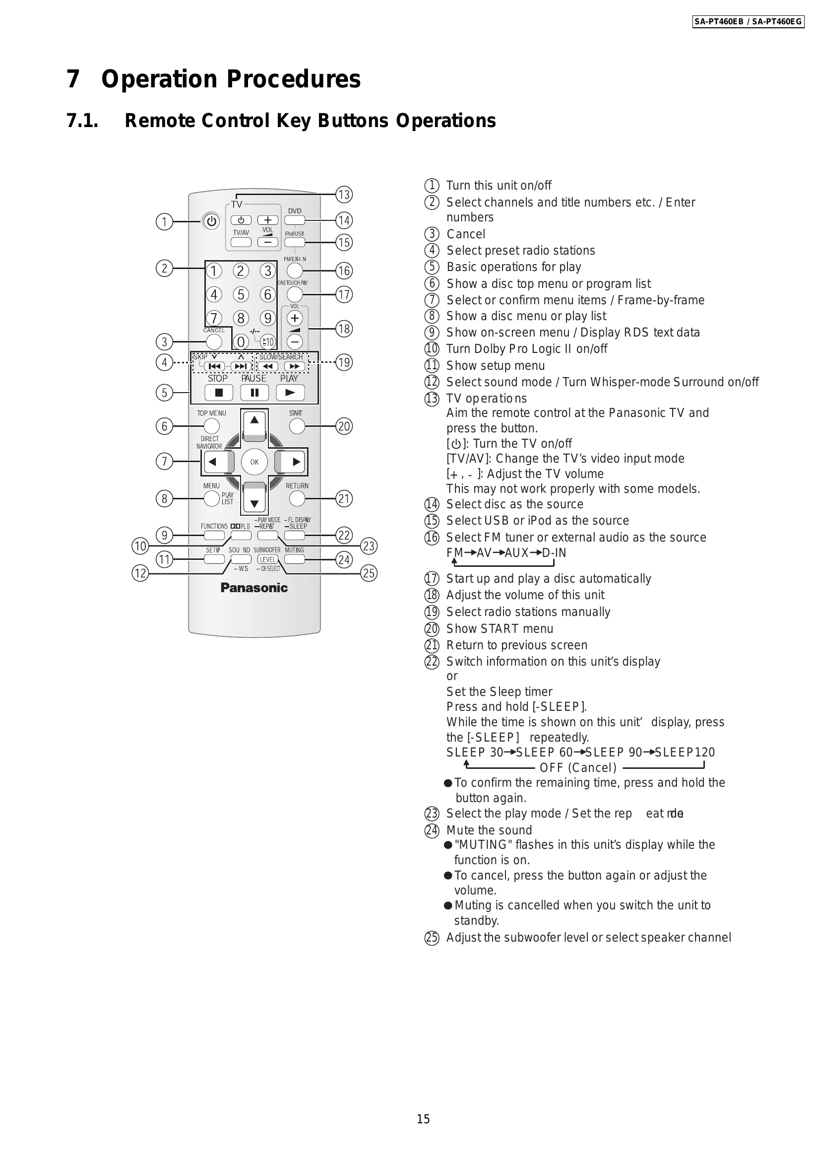
Remote Control Key Buttons Operations:
Main Unit Key Buttons Operations:
VIERA Link "HDAVI Control™": Enables linked operations between the unit and a Panasonic TV (VIERA) via HDMI. Supports "One Touch Play" and "Auto Input Switching".
USB Connection: Connect and play music, photos, and videos from USB mass storage devices. Supports MP3, WMA, JPEG, and MPEG4 (EG only). Ensure data is backed up and disconnect iPod before connecting USB.
| Symptom | Checking Items | Repair Items | Remarks |
|---|---|---|---|
| FL display blinking with abnormal segment when power ON the set or "F61" | Check the soldering of the SMPS P.C.B. Is there any solder crack at area (Q5860,Q5861, Q5862,TH5860, QR5801) Check all the supply line < 30V Is there any solderability at area of feedback circuit Check feedback circuit (IC5801, Q5802, D5806, PC5720, D5725) |
Touch-up the solder crack area/ Change the defective parts. Q5860,Q5861,Q5862,TH5860 (Temperature Detect) QR5801 & QR5802 (< 30V Detect) Touch-up the necessary areas IC5801, D5806, PC5720, D5725 |
SMPS P.C.B. Refer to Fig. 1 |
| First Power ON Display immediate show "F61". | Check Speaker output by using multi-meter, If there is a DC Voltage around < 30V Check Output IC (Pin 10 & 14) which have DC Voltage at Speaker output short to Vdd/Vss If shorted that means D-Amp damage already. |
Change the defective parts. D-AMP IC: IC5000/IC5200/IC5300/IC5400 P/N = C1BA00000487 For Configuration Refer to Table 1 |
D-AMP P.C.B. Refer to Fig. 2 |
| Power ON for a while then only trigger "F61". (Symptom always happen) | Check the fan connection & feedback loop: If the fan not proper connected, "F61" will trigger when the volume increase. If the fan is not working, check for fan circuit. Check the soldering of the SMPS P.C.B. Is there any solder crack at area (Q5860,Q5861, Q5862,TH5860, QR5801) Check all the supply line < 30V |
Re-connect the Fan to CN5501 Fan circuit: Q5640, Q5641, Q5642, Q5644 Touch-up the solder crack area/ Change the defective parts. Q5860,Q5861,Q5862,TH5860 (Temperature Detect) QR5801 & QR5802 (< 30V Detect) Feedback Circuit: IC5801, PC5720, D5725 |
D-AMP P.C.B. Refer to Fig. 3 |
| Power ON for a while and then trigger "F76" | Check all supply voltages as follows: Step 1: Check for supply voltages from SMPS P.C.B to Power Supply P.C.B at pin 8 & 9 of CN2004. If there are supply voltages, proceed to Step 2. If no voltages detected, check wire connection and circuitry connection from SMPS P.C.B. Step 2: Check if there is supply voltages for <Vp, F+ & F- at CN2016 If there is supply voltages of +5.3V, +2.5V (For DVD), +6V (SYS6V), +9V & +18V at CN2016 If there is supply voltages of <7V at CN6001 |
Check and change the possible defective parts. FP2901 (Fuse Protector), T2900, D2901, D2906, D2908, D2909 IC2903 (DC-DC Converter IC) & related regulator circuit components IC2900 (DC-DC Converter IC) & related regulator circuit components |
Power Supply P.C.B Refer to Fig. 4 |