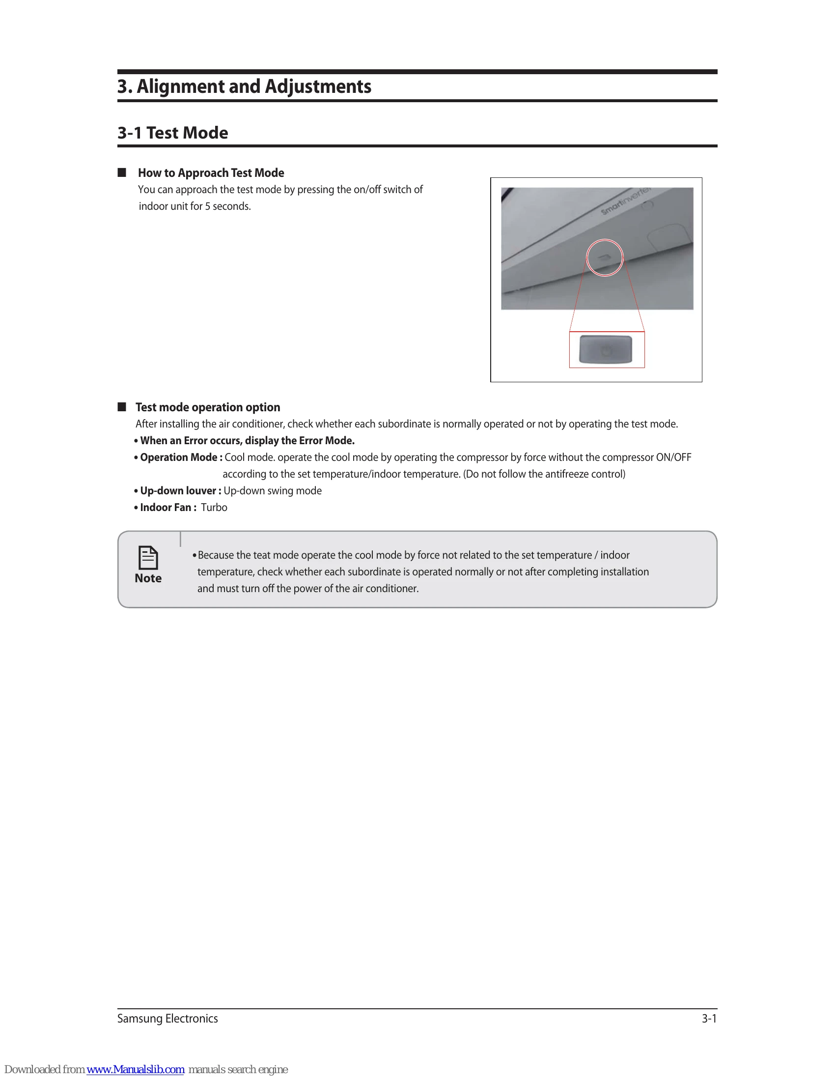
Brand: SAMSUNG
Category: Air Conditioner
Document Type: Manual
Language: EN
Brand: SAMSUNG
Category: Air Conditioner
Document Type: Manual
Language: EN
Uploaded: Nov. 21, 2025, 9:26 p.m.
Manual Publish Date: 2013-08-01
| No | Procedure | Inspection Method | Cause |
|---|---|---|---|
| 1 | Plug out and pull the PCB out of the control box Check the PCB fuse |
1) Is 1st fuse disconnected? 2) Is 2nd fuse disconnected? |
. Over current . Indoor Fan motor short . AC part and pattern short of Indoor PBA |
| 2 | Supply power If the operating lamp twinkles at this time, the above 1) ~ 3) have no relation |
Check the power voltage 1) Is the BD71 input voltage 200Vac~240Vac? 2) Is the voltage between both terminal of IC02 pin #1-#2 12Vdc? 3) Is the voltage between both terminal of IC02 pin #2-#3 5Vdc? |
. Power cord is fault, Fuse open, Wrong Power cable Wiring, AC part is faulty . Switching Trans of Power circuit is faulty . Power circuit is faulty, Load short |
| 3 | Press the ON/OFF button 1. Fan speed(high) 2. Continuous Operation |
1) Is the voltage over AC 180V being imposed on terminal #3-#5 of fan motor connector (CN72)? 2) The fan motor of the indoor unit doesn't run 3) The power voltage between terminal #3-#5 of the connector(CN72) is OV |
. Fan motor of the indoor is faulty . Fan motor connector (CN72) is faulty . PBA is faulty |
| 1 | Plug out and pull the PCB out of the control box Check the PCB fuse (Wait 3 minutes after power off) |
1) Is 1st fuse disconnected? | . Over current . AC part and pattern short of Outdoor PBA |
| 2 | Check the Wiring | 1) Is the Compressor wire connected clock-wise? 2) Is the Reactor wire connected normal? 3) Is the Fan wire connected normal? 4) Is the 4way wire connected normal? 5) Is the sensor wire connected normal? 6) Is the EEV wire connected normal? |
. Wrong assembly . Installation (service) condition is bad |
| 3 | "Supply power and operate the set" (Use Remote-control, button in indoor set) |
Check the power voltage 1) Is the voltage between Terminal block L-N 200Vac~240Vac? 2) Is the C006 voltage 200Vac~240Vac? 2) Is the CN150 voltage 200Vac~240Vac? 4) Is the PFC050(#26-#27) voltage 200Vac~240Vac after 3 minutes later? 5) Is the CE101 voltage 280Vdc~320dc after 3 minutes later? 6) Is the voltage CN151 #1-#2 voltage 15Vdc? 7) Is the voltage CN152 #1-#2 voltage 12Vdc? 8) Is the voltage CN151 #3-#2 voltage 5Vdc? |
. Power cord is faulty, Wrong Power cable Wiring . Fuse open . L,N,F1,F2 wire wrong wiring (Terminal Block-PBA) . Power circuit is faulty . Load short . Fuse open . L,N,F1,F2 wire wrong wiring (Terminal Block-PBA) . PTC020 open . RY021, RY022 is faulty . Outdoor Micom (IC201) error .PFC050 is faulty Reactor wire is wrong connection . Power circuit is faulty, Load short . BLDC Fan motor error Switching Trans of Power circuit is faulty . Load short . Switching Trans of Power circuit is faulty . Load short . Switching Trans of Power circuit is faulty . Load short |
| 4 | Check the LED lamp display | 1) Normal: RED on, GRN blink, YEL off 2) Abnormal - All off: check no power - abnormal display: check error mode |
. F1,F2 wire wrong wiring . Outdoor PBA is faulty |