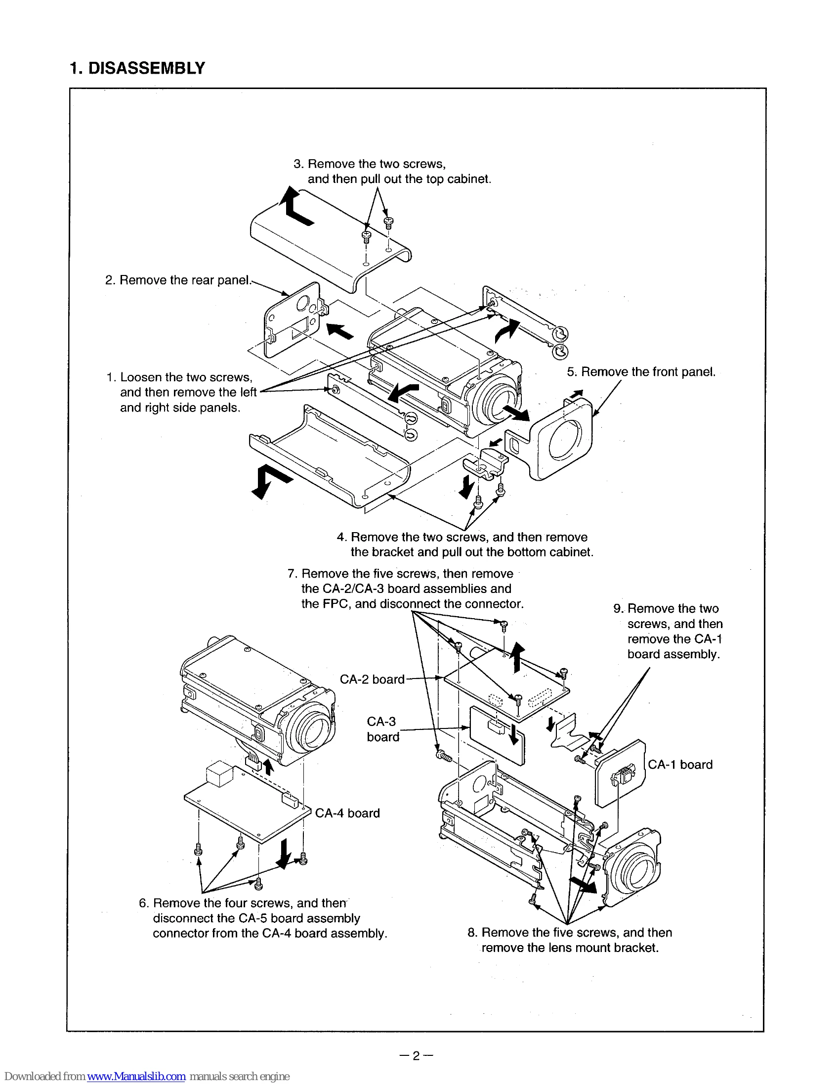
Brand: SANYO
Category: Camcorder
Document Type: Manual
Language: EN
Brand: SANYO
Category: Camcorder
Document Type: Manual
Language: EN
Uploaded: Nov. 21, 2025, 9:13 p.m.
| Adjustment Location | Measuring Location | Measuring Equipment | Subject | Adjusting Method |
|---|---|---|---|---|
| VR403 (CA-4) | TP403 (CA-4) | Digital voltmeter | No designation | Adjust with VR403 to 3.42 ± 0.02 V. |
| CT221 (CA-2) | TP221 (CA-2) | Frequency counter | No designation | Adjust with CT221 to 4433619 Hz ± 10 Hz. |
| CT232 (CA-2) | TP232 (CA-2) | Digital voltmeter | No designation | Adjust with CT232 to 8.0 ± 0.2 Vp-p. |
| Computer screen | VIDEO OUT | Oscilloscope | Gray scale chart | Follow adjustment software steps to adjust AGC for 750 ± 10 mVp-p output. |
| S3002-8, VR302, VR303 (CA-3) | VIDEO OUT | Oscilloscope, Vectorscope | Color bar chart | Set S3002 to MANUAL (ON), adjust VR302/VR303 for white spot alignment. |
| S3002-8 (CA-3), computer screen | VIDEO OUT | Oscilloscope, Vectorscope | Color bar chart | Follow software steps to adjust R GAIN, B GAIN, R HUE, B HUE for color spot alignment. Set S3002 to AUTO (OFF). |
| S3001, VR301 (CA-3) | VIDEO OUT | Oscilloscope | Gray scale chart | Set S3001 to DC type lens side. Adjust VR301 for max white level, then 750 ± 10 mVp-p output. |
| S3002-9 (CA-3), VR402 (CA-4) | VIDEO OUT, 24 V AC/GND terminals | Oscilloscope | Attach the lens cap | Set S3002-9 to L-L (ON). Adjust VR402 for 0 ± 0.2 msec sync signal/AC 24V zero-cross shift. Set S3002-9 to INT (OFF) before shipment. |
| FLANGE BACK ADJ. screw | Monitor display | Monitor display | Siemens star chart | Loosen lock screw, set zoom lens to telephoto and focus, then to wide angle and focus with ADJ. screw. Repeat until focus is consistent. Tighten lock screw. |