Brand: TENTO
Category: Camera
Document Type:
Language: EN
Brand: TENTO
Category: Camera
Document Type:
Language: EN
Uploaded: Aug. 9, 2025, 11:45 p.m.
| Trouble | Cause | Camera | Remedy |
|---|---|---|---|
| Mirror fails to be locked in lower position during shutter cocking | Eccentric bushing (Fig. 12) turned out of true | Adjust locking of cam 4 (Fig. 12) by lever 3 with up to 0.2 mm clearance between lever and cam projection with shutter fully cocked. Perform adjustment by turning eccentric bushing with screw 2 loosed. In case dog 9 (Fig. 39) is worn out of true additionally disassemble camera as instructed in Par. 4.9. Unscrew screw 11 in cocking knob, remove dog 9 and replace it by new one. Install removed cocking knob in place as instructed in Par. 6.6 and check its locking. Assemble camera in sequence reverse to disassembling and adjust it as instructed in Pars 7.1-7.2. | |
| Curtains fail to operate | First curtain (Fig. 18) is damaged, tape (black) of first curtain is broken or second curtain 16 (Fig. 14) is damaged, tape (white) of second curtain is broken | Disassemble camera as instructed in Pars 4.1-4.12. Additionally disassemble shutter as instructed in Pars 5.1-5.7 to replace first curtain and Pars 5.8, 5.9 to replace second curtain. Assemble shutter as instructed in Pars 6.1-6.17 and adjust it as instructed in Pars 7.1, 7.2. Assemble and adjust camera as instructed in Section 8. | |
| Violated meshing of magazine gears with camera (movable tooth fails to enter recess) | Teeth of gear 29 (Fig. 14) worn out | Disassemble camera as instructed in Pars 4.1-4.5, 4.7-4.12, 5.1, 5.2. Unscrew screw 7 (Fig. 14) with left-hand thread and remove gear 6. Unscrew screw 4 loosen screw 7 (Fig. 16) and withdraw tie rod 32 (Fig. 14). Unscrew screw 25, remove gear 29 and replace it with new one. Assemble and adjust shutter as instructed in Pars 6.6; 6.15-6.17. Assemble and adjust camera as instructed in Section 8. | |
| In cocking the shutter knob fails to be locked against reverse turning | Spring 5 (Fig. 14) revolves or pawl 3 is tight to rotate on axle | Disassemble camera as instructed in Pars 4.1-4.12. Unscrew screw 7 (Fig. 14), remove gear 6. spring 5. wash and crimp the spring. Wash pawl 3, lubricate friction points with oil MH-30 and adjust smoothness of rotation. Assemble parts in sequence reverse to disassembling. Assemble shutter as instructed in Par. 6.6 and check interlocking. Assemble and adjust camera as instructed in Section 8. | |
| Exposure time is out of tolerance | Violated positions of impeller 9 (Fig. 25), eccentric pin 1 or eccentric pin of dog 13 (Fig. 17) | Disassemble camera as instructed in Pars 4.1-4.12. Fit cocking knob onto shutter as instructed in Par. 6.6. Adjust exposure time as instructed in Pars 7.1, 7.2. Assemble and adjust camera as instructed in Section 8. | |
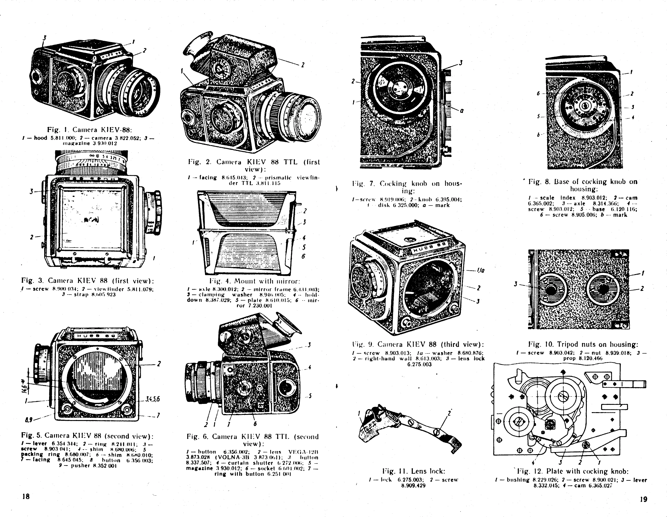
| Lens diaphragm fails to be fully opened in cocking the camera | Upset dimension (14.6-0.1) mm between lever 1 (Fig. 5) and bearing ring 2 (Fig. 5) and bearing ring 2 | Remove lens from camera as instructed in Par. 4.1. Measure with depth gauge 8511-4001 dimension (14.6-0.1) mm from bearing surface of lever 1 with shutter cocked and adjust it by installing washers 3 (Fig. 20) under screw 2 with |