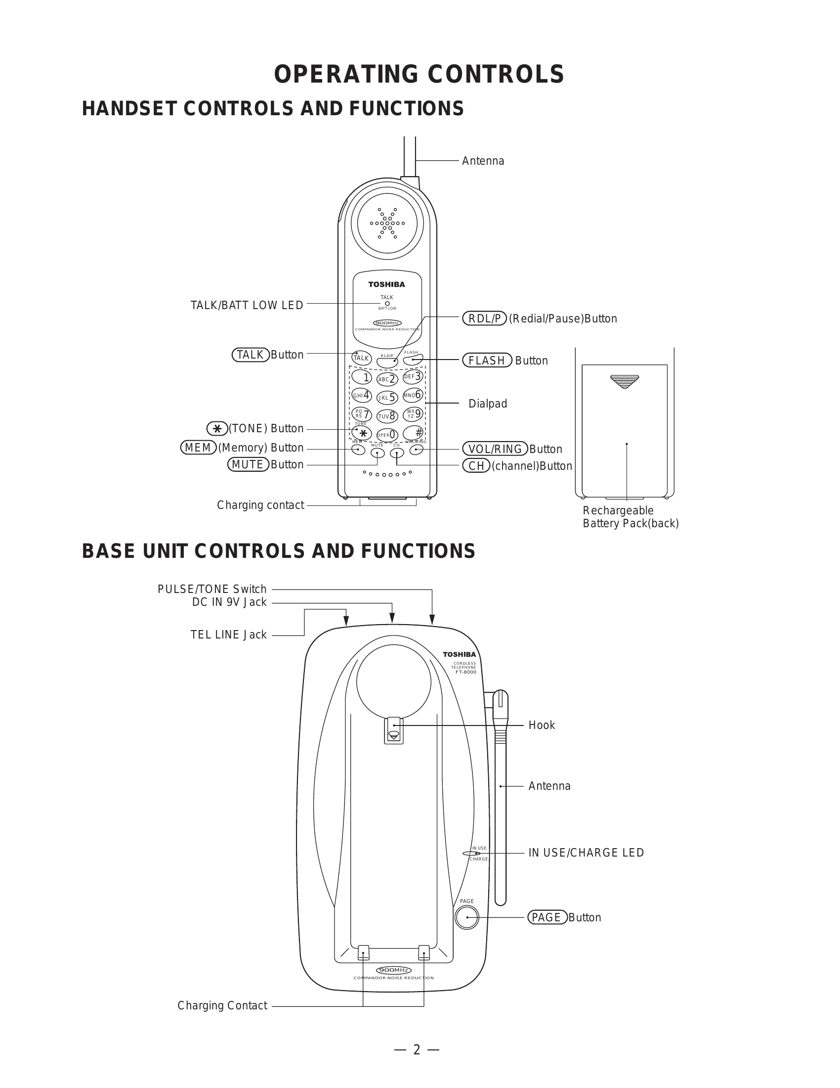
Brand: TOSHIBA
Category: Telephone
Document Type: Manual
Language: EN
Brand: TOSHIBA
Category: Telephone
Document Type: Manual
Language: EN
Uploaded: Nov. 21, 2025, 7:03 p.m.
Manual Publish Date: 2000-08-01
null
| Issue | Symptom | Possible Cause/Action |
| 1. The bell does not ring. | When the PAGE SW of the base is pressed, does the ringer on the handset ring? | NG: See 2. The bell does not ring & page does not ring. OK: When the TEL SG is joined with the base to make bell signal, is there pulse wave at pin 4 of IC4? NG: Check IC4 and TEL network circuit. OK: Is there pulse wave at pin 21 of IC5? NG: Check R58, C45 and R59. OK: Check IC5 and its peripheral circuit. |
| 2. The bell does not ring & page does not ring. | Can the base and handset be connected? | NG: See 3. The base and handset cannot be connected. OK: Press handset DIAL key while in TALK MODE. Can key touch sound be heard from the ringer? NG: Check IC604. OK: At the Q608 collector, can the pulse wave be seen? NG: Check R654, R657 and D602. OK: Check RINGER SP601. |
| 3. The base and handset cannot be connected. | Check whether the base is able to set in the test mode 1. | NG: Check IC5 and its peripheral circuit. OK: Check the TX POWER and the TX FREQUENCY on the base unit. NG: Check base RF unit. OK: Set the base in the test mode 3, check whether deviation of the TX data is app. 8 kHz Dev. NG: Check whether there is a 250 Hz data waveform at "MOD" of RF unit. NG: Check base RF unit. OK: Check RT3, R40, R68, R69, R53, R70 and C79. OK: Set the base in the test mode 8, 902.952467 MHz (250 Hz ±8 kHz Dev.) 1mV output signal from RF jack is applied. Can the status LED be lighted? NG: Check whether there is a 250 Hz data waveform at pin 9 of IC3. NG: Check IC3, Q1 and their peripheral circuit. OK: Check base RF unit. OK: Check whether there is a 250 Hz data waveform at the Q2 collector. NG: Check RT2, Q2 and their peripheral circuit. OK: Check whether there is a 250 Hz data waveform at pin 38 of IC5. NG: Check R42, R46, IC1 and their peripheral circuit. OK: Check IC5 and its peripheral circuit. OK: Check whether the handset is able to set in the test mode 1. NG: Check IC604 and its peripheral circuit. OK: Check the TX POWER and the TX FREQUENCY on the handset unit. NG: Check handset RF unit. OK: A |
| 4. Cannot make a phone call (pulse). | Can the base and handset be connected? | NG: See 3. The base and handset cannot be connected. OK: While in TALK MODE, press dial key of the handset. Check whether square waveform from pin 13 of IC5 is fed. NG: Check IC5. OK: Check Q10, RL1 and their peripheral circuits. |
| 5. Cannot make a phone call (tone). | Can the base and handset be connected? | NG: See 3. The base and handset be cannot be connected. OK: While in TALK MODE, press dial key of the handset. Can tone waveform from Pin 1 of IC5 is fed? NG: Check IC5. OK: Can tone signal be heard from the handset speaker? NG: Check IC1, Q3 and their peripheral circuits. OK: Check the base TEL-line circuit and RELAY control circuit. |
| 6. Voice cannot be transmitted to other party (outgoing call). | Can the base and handset be connected? | NG: See 3. The base and handset cannot be connected. OK: The 1 kHz, 9.0mV sine waveform is applied to MC601 side, can the 1 kHz sine waveform from pin 24 of IC603 be fed? NG: Check Q604 and its peripheral circuit. OK: Check whether there is the 1 kHz sine waveform at pin 23 of IC603. NG: Check IC603 and its peripheral circuit. OK: Check whether there is the 1 kHz sine waveform at pin 20 of IC603. NG: Check IC603 and its peripheral circuit. OK: TX output signal from the handset is detected by the liner detector, can the 1 kHz sine waveform be fed? NG: Check RT603 or handset RF unit. OK: Check whether there is the 1 kHz sine waveform at pin 9 of IC3 on the base unit. NG: Check IC3, Q1 and their peripheral circuit. NG: Check base RF unit. OK: OK: Check whether there is the 1 kHz sine waveform at pin 3 of IC1. NG: Check RT2, Q2 and their peripheral circuits. OK: Check whether there is the 1 kHz sine waveform at pin 18 of IC1. NG: Check IC1 and its peripheral circuit. OK: Check whether there is the 1 kHz sine waveform at the Q3 collector. NG: Check Q3 and its peripheral circuit. OK: Check whether the 1 kHz sine waveform from TEL-line output is fed. NG: Check T1, RL1 and their peripheral circuits. OK: Check MC601 of handset. |
| 7. The voice of the caller cannot be heard (incoming call). | Can the base and handset be connected? | NG: See 3. The base and handset cannot be connected. OK: The 1 kHz, 138mV sine waveform is applied to TEL-line of the base, can the 1 kHz sine waveform from the Q3 collector be fed? NG: Check Q4 and its peripheral circuit. OK: Check whether there is the 1 kHz sine waveform at pin 24 of IC1. NG: Check IC1 and its peripheral circuit. OK: Check whether there is the 1 kHz sine waveform at pin 20 of IC1. NG: Check RT3 and its peripheral circuit. OK: Check whether there is the 1 kHz sine waveform at "MOD" RF unit. NG: Check base RF unit. OK: TX output signal from the base is detected by the liner detector, can the 1 kHz sine waveform be fed? NG: Check IC601, Q601 and their peripheral circuit. NG: Check handset RF unit. OK: OK: Check whether there is the 1 kHz sine waveform at pin 3 of IC603. NG: Check RT602, Q602 and their peripheral circuits. OK: Check whether there is the 1 kHz sine waveform at the pin 18 of IC603. NG: Check IC603 and its peripheral circuit. OK: Check whether there is the 1 kHz sine waveform at pin 1, 2 of SP801. NG: Check Q605, Q606 and its peripheral circuit. OK: Check SP801 and W801, W802. |