Brand: TOSHIBA
Category: Telephone
Document Type: Manual
Language: EN
Brand: TOSHIBA
Category: Telephone
Document Type: Manual
Language: EN
Uploaded: Nov. 21, 2025, 6:46 p.m.
Manual Publish Date: 1999-08-01
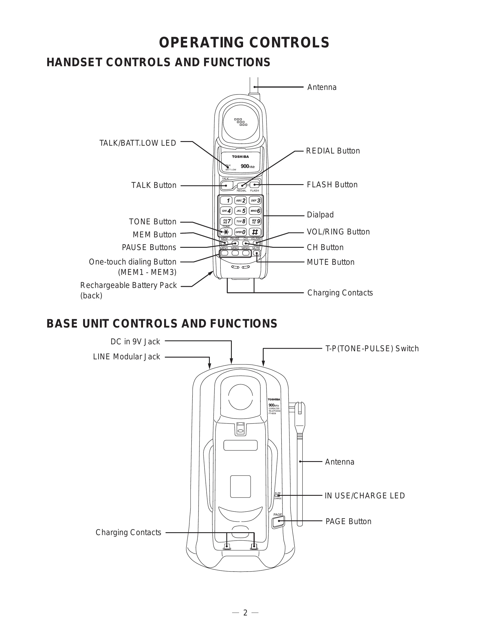
TALK/BATT.LOW LED: Indicates talk status and low battery.
TALK Button: Initiates or ends a call.
TONE Button: Switches to tone dialing.
MEM Button: Stores phone numbers for one-touch dialing.
PAUSE Buttons: Inserts pauses in dialing sequences.
One-touch dialing Buttons (MEM1 - MEM3): Dials pre-programmed numbers.
Rechargeable Battery Pack (back): Removable battery pack.
Antenna: For wireless communication.
REDIAL Button: Redials the last number called.
FLASH Button: Used for call waiting or other network functions.
Dialpad: For entering phone numbers.
VOL/RING Button: Adjusts the volume or ringer level.
CH Button: Channel selection (if applicable).
MUTE Button: Mutes the microphone during a call.
Charging Contacts: For charging the handset on the base.
DC in 9V Jack: Power input for the base unit.
LINE Modular Jack: Connects to the telephone line.
T-P(TONE-PULSE) Switch: Selects dialing mode (Tone or Pulse).
Charging Contacts: For charging the handset.
Antenna: For wireless communication.
IN USE/CHARGE LED: Indicates if the base is in use or charging the handset.
PAGE Button: Locates the handset.
| No. | Symptom | Possible Cause | Solution |
|---|---|---|---|
| 1 | The bell does not ring. | PAGE SW pressed, ringer on handset not ringing. | See 2. The bell does not ring & page does not ring. |
| TEL SG joined, no pulse wave at pin 4 of IC4. | Check IC4 and TEL network circuit. | ||
| No pulse wave at pin 21 of IC5. | Check R58, C45 and R59. | ||
| Issue with IC5 and its peripheral circuit. | Check IC5 and its peripheral circuit. | ||
| 2 | The bell does not ring & page does not ring. | Base and handset not connected. | See 3. The base and handset cannot be connected. |
| Handset DIAL key pressed in TALK MODE, key touch sound not heard. | Check IC5. | ||
| Key of handset pressed, no pulse output at pin 38 of IC404. | Check IC404. | ||
| No pulse wave at Q408 collector. | Check R454, R457 and D402. | ||
| Issue with RINGER Y401. | Check RINGER Y401. | ||
| PAGE SW pressed, pin20 of IC5 does not change. | Check R55, R77 and S1. | ||
| Issue with IC5 and its peripheral circuit. | Check IC5 and its peripheral circuit. | ||
| 3 | The base and handset cannot be connected. | Base not setting to test mode 1. | Check IC5 and its peripheral circuit. |
| TX POWER/FREQUENCY issue on base unit. | Check base RF unit. | ||
| Base in test mode 3, deviation not approx. 8 kHz Dev. | Check RT3, R40, R68, R69, R53, R70 and C79. | ||
| No 250 Hz data waveform at "MOD" of RF unit. | Check base RF unit. | ||
| No 250 Hz data waveform at pin 9 of IC3. | Check IC3, Q1 and their peripheral circuit. | ||
| No 250 Hz data waveform at Q2 collector. | Check RT2, Q2 and their peripheral circuit. | ||
| No 250 Hz data waveform at pin 38 of IC5. | Check R42, R46, IC1 and their peripheral circuit. | ||
| Issue with IC5 and its peripheral circuit. | Check IC5 and its peripheral circuit. | ||
| Handset not setting to test mode 1. | Check IC404 and its peripheral circuit. | ||
| TX POWER/FREQUENCY issue on handset unit. | Check handset RF unit. | ||
| Handset in test mode 3, deviation not approx. 8 kHz Dev. | Check RT403, R441, R442, R443, R444, R445 and C453. | ||
| No 250 Hz data waveform at "MOD" of RF unit. | Check handset RF unit. | ||
| Handset in test mode 6, 1mV output signal applied, bell not ringing. | Check IC401, Q401 and their peripheral circuit. | ||
| No 250 Hz data waveform from pin 9 of IC401. | Check handset RF unit. | ||
| No 250 Hz data waveform at Q402 collector. | Check RT402, Q402 and their peripheral circuit. | ||
| No 250 Hz data waveform at pin 40 of IC404. | Check R428, R429, IC403 and their peripheral circuit. | ||
| Issue with IC404 and its peripheral circuit. | Check IC404 and its peripheral circuit. | ||
| 4 | Cannot make a phone call (pulse). | Base and handset not connected. | See 3. The base and handset cannot be connected. |
| Handset dial key pressed, no square waveform from pin 13 of IC5. | Check IC5. | ||
| Issue with Q10, RL1 and their peripheral circuits. | Check Q10, RL1 and their peripheral circuits. | ||
| 5 | Cannot make a phone call (tone). | Base and handset not connected. | See 3. The base and handset be cannot be connected. |
| Handset dial key pressed, no tone waveform from Pin 1 of IC5. | Check IC5. | ||
| Tone signal not heard from handset speaker. | Check IC1, Q3 and their peripheral circuits. | ||
| Issue with base TEL-line circuit and RELAY control circuit. | Check the base TEL-line circuit and RELAY control circuit. | ||
| 6 | Voice cannot be transmitted to other party (outgoing call). | Base and handset not connected. | See 3. The base and handset cannot be connected. |
| 1 kHz, 9.0mV sine waveform applied, no 1 kHz sine waveform from pin 24 of IC403. | Check Q404 and its peripheral circuit. | ||
| No 1 kHz sine waveform at pin 20 of IC403. | Check IC403 and its peripheral circuit. | ||
| No 1 kHz sine waveform at pin 23 of IC403. | Check RT403 and its peripheral circuit. | ||
| TX output signal not detected by liner detector. | Check handset RF unit. | ||
| No 1 kHz sine waveform at pin 9 of IC3 on base unit. | Check IC3, Q1 and their peripheral circuit. | ||
| No 1 kHz sine waveform at pin 3 of IC1. | Check RT2, Q2 and their peripheral circuits. | ||
| No 1 kHz sine waveform at pin 18 of IC1. | Check IC1 and its peripheral circuit. | ||
| No 1 kHz sine waveform at Q3 collector. | Check Q3 and its peripheral circuit. | ||
| 1 kHz sine waveform not fed from TEL-line output. | Check T1, RL1 and their peripheral circuits. | ||
| Issue with MC401 of handset. | Check MC401 of handset. | ||
| 7 | Voice of the caller cannot be heard (incoming call). | Base and handset not connected. | See 3. The base and handset cannot be connected. |
| 1 kHz, 77.5mV sine waveform applied, no 1 kHz sine waveform from Q3 collector. | Check the base TEL-line circuit and REPLAY control circuit. | ||
| No 1 kHz sine waveform at pin 24 of IC1. | Check Q4 and its peripheral circuit. | ||
| No 1 kHz sine waveform at pin 20 of IC1. | Check IC1 and its peripheral circuit. | ||
| No 1 kHz sine waveform at "MOD" RF unit. | Check RT3 and its peripheral circuit. | ||
| TX output signal not detected by liner detector. | Check base RF unit. | ||
| No 1 kHz sine waveform at pin 9 of IC401 on handset unit. | Check IC401, Q401 and their peripheral circuit. | ||
| Issue with handset RF unit. | Check handset RF unit. | ||
| No 1 kHz sine waveform at pin 3 of IC403. | Check RT402, Q402 and their peripheral circuits. | ||
| No 1 kHz sine waveform at pin 18 of IC403. | Check IC403 and its peripheral circuit. | ||
| No 1 kHz sine waveform at pin 1, 2 of SP801. | Check SP801 and W801, W802. | ||
| Issue with Q405, Q406 and its peripheral circuit. | Check Q405, Q406 and its peripheral circuit. |